FBOSS Requirements for NPO Switch
Scope
This document captures requirements to the FBOSS NPO system, including hardware architecture and software functions.
There are different levels of the requirements:
- Must Have (MH): The system must satisfy “must have” requirements. By default, all requirements are “must have” unless they are explicitly specified otherwise.
- Strong Desire (SD): The system must support “strong desire” requirements. There is a clear timeline when the requirements will be fully supported, if it is not supported yet. If the requirement is on HW and is not supported from HW EVT, which phase of HW NPI with respin or not must be approved by Meta.
- Wish List (WL): “Wish list” requirements are what Meta is evaluating. Any limitation on the system to support this type of requirements shall be explicitly stated by the system vendor.
Terminology
- OE = Optical Engine
- PLS = Pluggable Laser Source
- ELS = External Laser Source (interchangeable with PLS)
- ELSFP = External Laser Small Form Factor Pluggable (ELSFP and PLS are used interchangeably in this document)
- ILS = Internal Laser Source
- MCU = Microcontroller Unit
System Architecture
The overall requirement is to follow FBOSS BMC-Lite architecture for the switch or as communicated by Meta. The depictions below are examples of designs that can facilitate easier HW - SW integration between NPO modules and FBOSS software (i.e. QSFP service and LED Service). For more information about FBOSS requirements you can refer to Meta Switch Architecture.
Below are some of the possible designs for integrating NPO to a switch. Specific FBOSS requirements will follow.
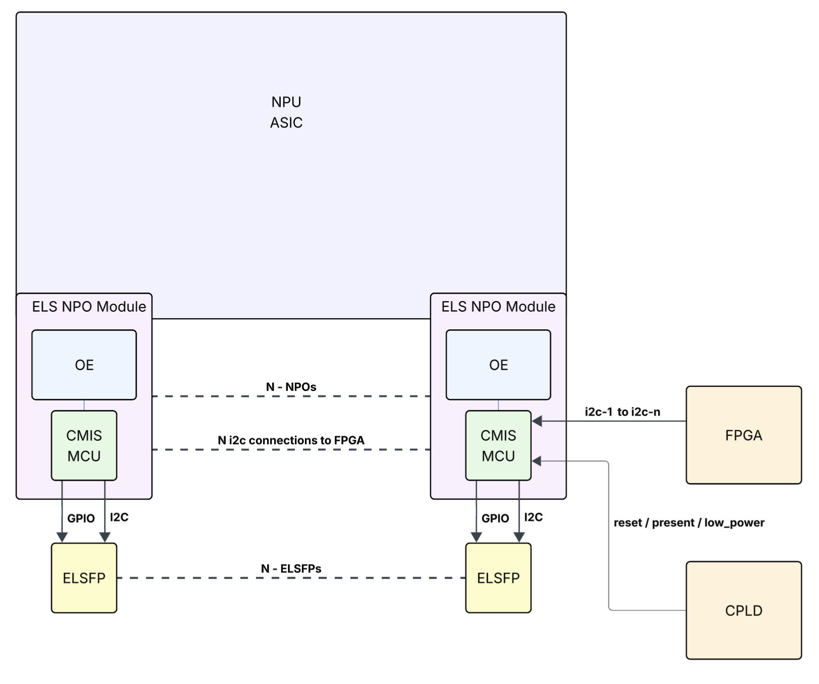
Diagram 1: NPO Hardware with ELS
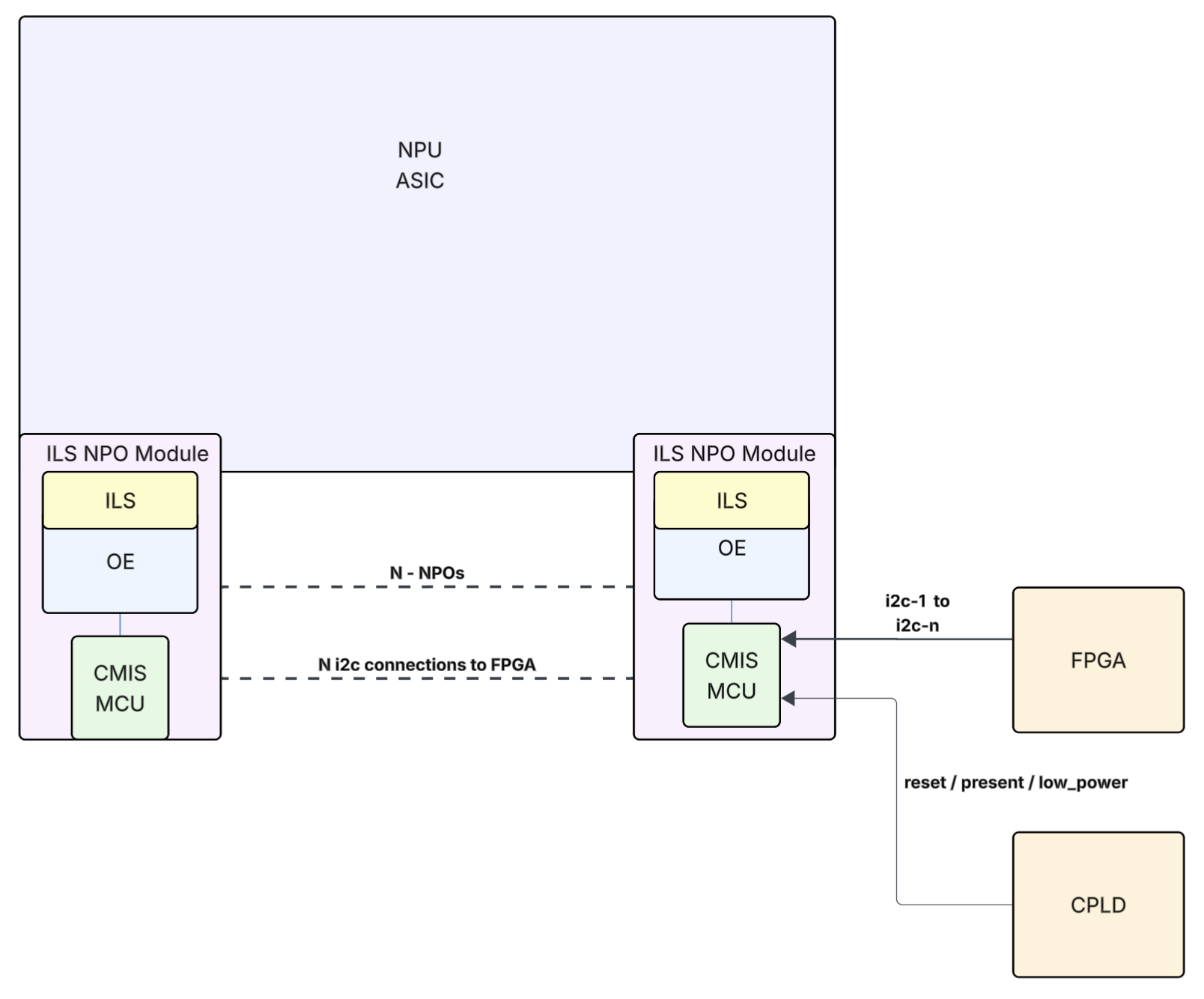
Diagram 2: NPO Hardware with ILS
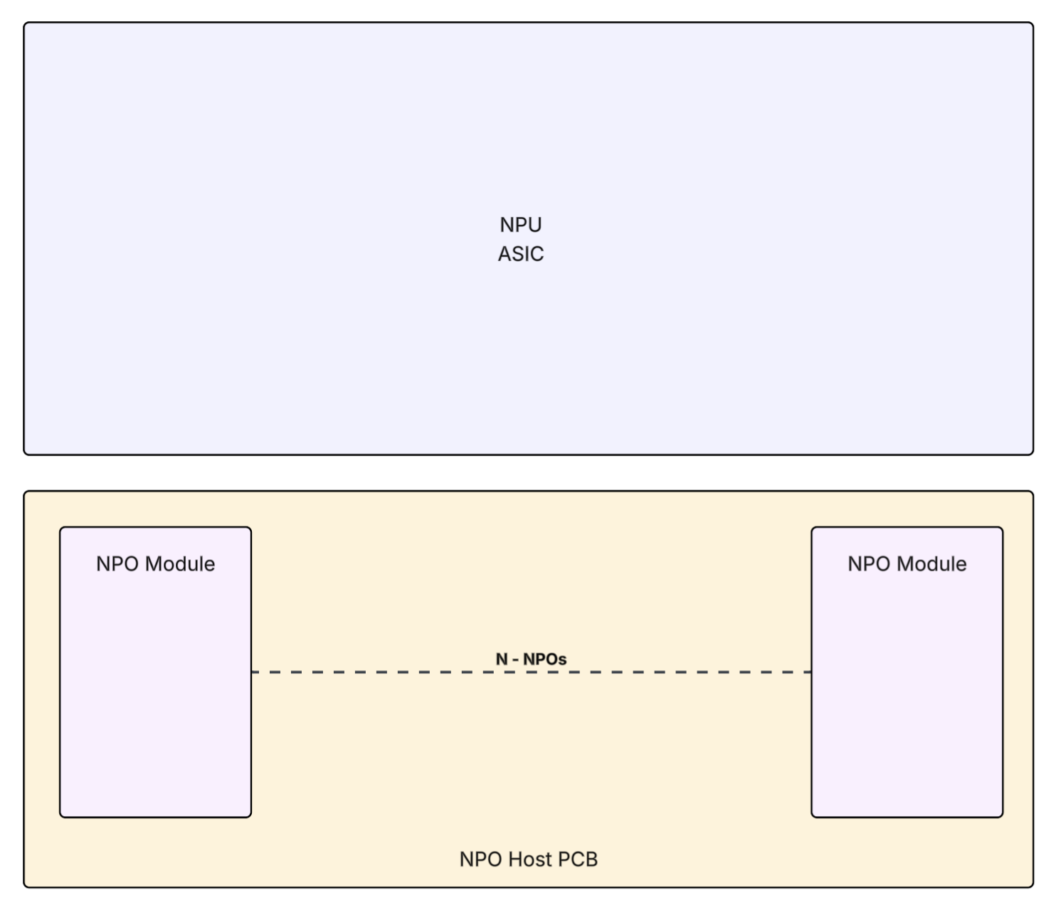
Diagram 3: NPOs with a Host PCB board
Hardware Requirements
NPO Vendor Integration
- The switch shall have a single vendor source/Part Number for all NPOs within a single switch, unless otherwise accepted by Meta.
OE and ELSFP Control Management
- The NPO shall have an MCU that implements the CMIS interface and abstracts the functioning of the Optical Engine and Pluggable Laser Source (if applicable) from the software.
- One NPO shall not support more than the maximum number of lanes supported by CMIS.
- In ELS design, there shall be a 1:1 mapping between an NPO and an ELSFP, since the software models the NPO as one pluggable device supporting one I2C interface from the ELSFP and its corresponding GPIO pins.
- As long as the switch is powered on, the software shall be able to communicate with the NPO MCU and program and monitor the OE and ELSFP constantly independent of the ASIC power-up/ready status.
- Different ELSFPs and/or different OE shall be transparent to the software, from the programming model aspect, except for tuning parameters.
NPO Optical Engine
- The OE should be capable of generating and checking PRBS on the optical line side (WL).
- The OE should be capable of generating and checking PRBS on the electrical system side (WL).
I2C
- Each NPO shall have a dedicated, non-shared I2C bus from the FPGA, supporting a minimum bus speed of 1 MHz.
GPIO
- The NPO shall expose the following pins to the CPLD/FPGA:
- Reset:
- A single reset pin that controls the reset of MCU, OE and ELSFP, regardless of their state.
- Resetting should bring the MCU, OE and ELSFP into a clean state as if just after power-on.
- Module Present:
- This pin should indicate the presence of the corresponding ELSFP.
- Low Power:
- This pin should enable and clear low power mode on both the OE and the ELSFP.
- Reset:
LEDs
- There shall be a tri-color (red, yellow, blue) front panel LED per front panel fiber port.
- The LEDs will be driven by FBOSS software through the FPGA/CPLD.
NPOs with a Host PCB Assembly
For designs that co-package the NPOs in a secondary PCB (Diagram 3); in case of presence of active components on the PCB (e.g. temperature sensors, voltage regulators, etc.):
- The BSP shall expose access for FBOSS software to those components for monitoring / programmability via Platform Manager.
- The NPO Host PCB shall incorporate a Meta EEPROM for the manufacturing and version details of the PCB in accordance with Meta EEPROM specifications.
FBOSS Software Requirements
I2C and GPIO access
- The BSP shall expose the same interfaces to software as it does for the pluggable optics. For example:
/run/devmap/xcvrs/xcvr_io_1/run/devmap/xcvrs/xcvr_ctrl_1/xcvr_reset_1/run/devmap/xcvrs/xcvr_ctrl_1/xcvr_present_1
- Software will communicate with the CMIS MCU over I2C using linux standard ioctl calls to
/run/devmap/xcvrs/xcvr_io_X. - The BSP shall expose the interfaces for LED programming for colors (blue and amber) and blink capability.
- For the complete and most recent BSP specification, refer to https://meta.github.io/fboss/docs/platform/bsp_api_specification/
CMIS
- The NPO shall support CMIS 5.3 or newer.
- The NPO shall not support more than the maximum lanes defined by CMIS.
- For example, CMIS 5.3 supports core management features on 4 x 8 lanes.
Datapath Programming
- Software shall only communicate with the NPO for reading, programming and monitoring. Any internal calibration or communication between OE or ELSFP shall be orchestrated by the NPO firmware and shall be transparent to FBOSS software.
- The time needed to finish the internal calibration shall be within the advertised time for datapath initialization defined in byte 144 in page 01h in CMIS 5.3.
- The NPO shall implement the CMIS standard Module State Machine and Datapath State Machine, exposing the same control registers for datapath programming as a standard pluggable transceiver.
- All NPO devices on the switch shall be independently and simultaneously programmable in a multi-threaded environment.
- The cumulative time for completing datapath programming and achieving link up for all NPO ports on the switch shall be less than 10 seconds.
Features
Firmware Upgrade: NPO and ELSFP
- Software will use the CMIS MCU to upgrade firmware for various components (CMIS MCU, OE, and ELSFP) via standard CDB procedures.
- The cumulative time for firmware upgrade of all components - including all MCUs, all OEs and all ELSFPs - should be between 5 minutes (SD) and 10 minutes (MH).
- If the firmware upgrade for NPO is interrupted, the component shall recover itself with the old firmware automatically after a reset.
- There shall be only 1 firmware file to upgrade any/all internal components to the NPO.
- ELSFP FW upgrade shall be completed through the NPO MCU via CDB commands.
ELSFP Monitoring
- The CMIS MCU shall be able to read all diagnostics from the ELSFP as if it were reading the same diagnostics from a pluggable optic.
- The CMIS MCU shall mirror ELSFP diagnostics into the corresponding DOM offsets in the standard upper pages defined in CMIS.
- In addition, the CMIS MCU shall memory-map the ELSFP EEPROM in the reserved upper pages on bank 0. Ideally, the contents of the monitors in the ELSFP pages and the standard upper pages should match, but any differences will be used for debugging purposes.
- The CMIS MCU shall expose read-only access to the ELSFP pages in the above reserved upper pages.